Two Wheel
A localizer that uses two odometry wheels
Prerequisites
- Two odometry wheels connected to motor encoder ports on a hub. One odometry wheel should be parallel to your robot's wheels, while the other should be perpendicular the the robot's wheels.
- A properly configured IMU.
Default Values
These are the default values of the TwoWheelConstants. Copy and paste this into your Constants file:
    public static TwoWheelConstants twoWheelConstants = new TwoWheelConstants()
            .forwardTicksToInches(.001989436789)
            .strafeTicksToInches(.001989436789)
            .forwardY(1)
            .strafeX(2.5)
            .forwardEncoder_HardwareMapName("leftFront")
            .strafeEncoder_HardwareMapName("rightRear")
            .forwardEncoderDirection(Encoder.REVERSE)
            .strafeEncoderDirection(Encoder.FORWARD)
            .IMU_HardwareMapName("imu")
            .IMU_Orientation(new RevHubOrientationOnRobot(RevHubOrientationOnRobot.LogoFacingDirection.UP, RevHubOrientationOnRobot.UsbFacingDirection.LEFT));
Steps
1. Switch to having a twoWheelLocalizer in the createFollower method.
- In the
createFollowermethod, make sure that theFollowerBuilderreturned has the desiredtwoWheelLocalizer.
    public static Follower createFollower(HardwareMap hardwareMap) {
        return new FollowerBuilder(followerConstants, hardwareMap)
                .mecanumDrivetrain(driveConstants)
                .twoWheelLocalizer(twoWheelConstants)
                .pathConstraints(pathConstraints)
                .build();
    }
1. Odometry Wheel Setup
Open the file Constants and navigate to TwoWheelConstants. Configure the following:
Encoder Ports:
- Replace the
forwardEncoder_HardwareMapNameandstrafeEncoder_HardwareMapNamewith the names of the ports connected to your encoders (odometry). The names will match the hardware map names of the motor port that they are connected to. - The
forwardEncoder_HarwareMapNameshould be the name of the port connected to the odometry pod parallel to your wheels. - The
strafeEncoder_HardwareMapNameshould be the name of the port connected to the odometry pod perpendicular to your wheels.
Odometry Measurements:
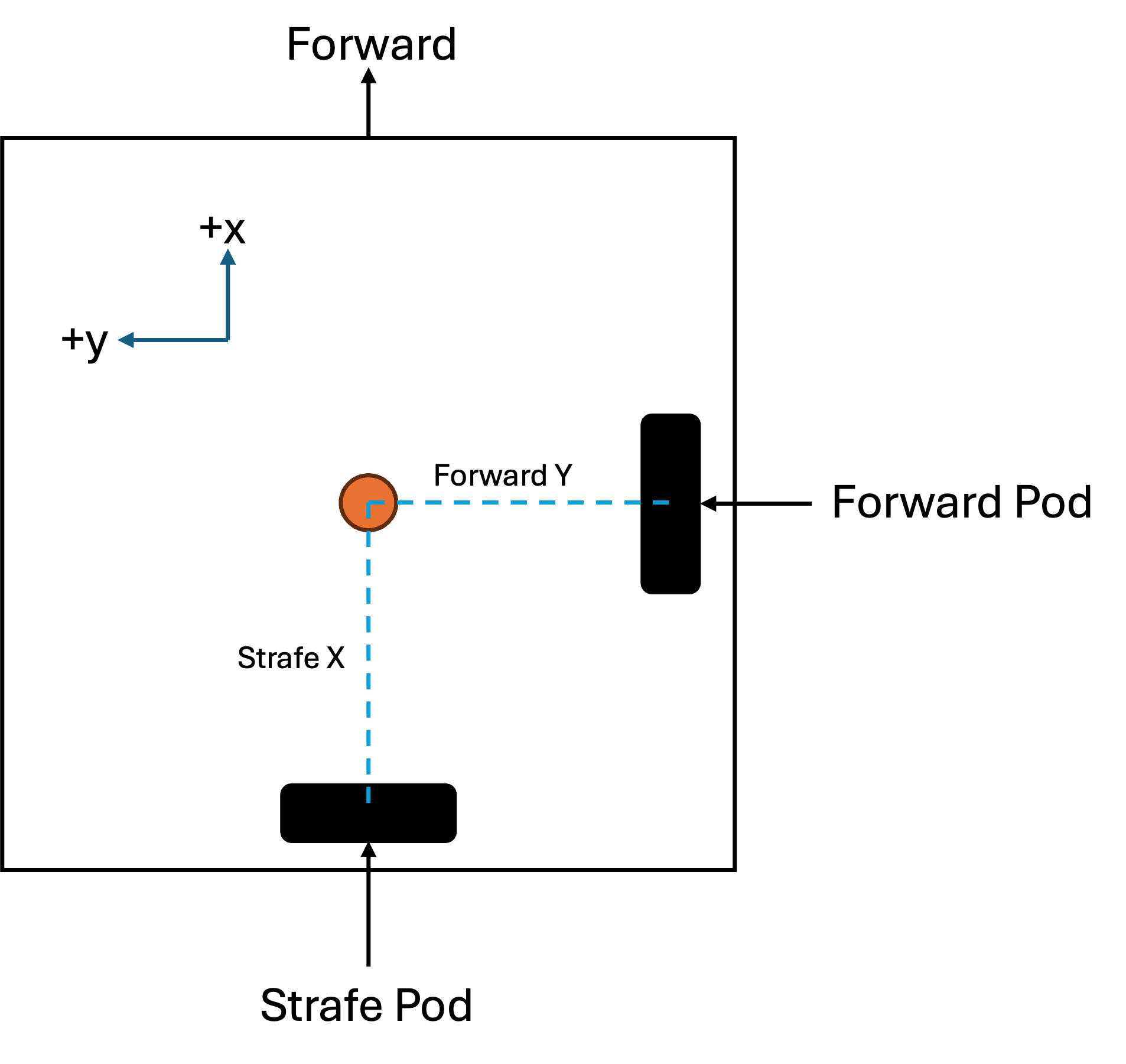
- Input the
forwardYandstrafeXvalues. - These values represent the distance of the odometry wheels from the robot's center of rotation on the robot coordinate grid in inches.
- Use this diagram to find the signs these distances. This view is from the top of the robot looking downwards.
Encoder Directions:
- The Encoder Directions can be changed by switching between
Encoder.REVERSEandEncoder.FORWARDforforwardEncoderDirectionorstrafeEncoderDirection. - Run the
Localization Testand observe the encoder values. - If the x value ticks down when the robot moves forward, reverse the direction of the forward pod.
- If the y value ticks down when the robot moves left, reverse the direction of the strafe pod.
IMU Setup:
- Replace the
IMU_HardwareMapNamewith the name of the configuration for your IMU. - Note: Make sure that if you are using the control hub's built-in IMU, you have it configured to port 0 on the control hub.
- Define the orientation of the IMU on the robot by changing the
RevHubOrientationOnRobotvalue forIMU_Orientation. - Refer to this resource to determine your IMU's
LogoFacingDirectionandUsbFacingDirection.
2. Localizer Tuning
We need to adjust multipliers that convert encoder ticks into real-world measurements: inches. This ensures your localizer's readings are accurate.
a. Forward Localizer Tuner
-
Position a ruler alongside your robot.
-
Run the
Forward Localizer Tuneropmode. -
Push the robot forward by the desired distance (default is 48 inches).
-
The tuner will display two numbers:
-
First number: Distance the robot thinks it has traveled.
-
Second number: the
multiplier -
(Optional) Run multiple tests and average the multipliers for better accuracy.
- Input this value in
ConstantsasforwardTicksToInches = [multiplier], where[multiplier]is the value you obtained from the tuner.
b. Lateral Localizer Tuner
-
Position a ruler alongside your robot.
-
Run the
Lateral Localizer Tuneropmode. -
Push the robot sideways (strafing) by the desired distance (default is 48 inches).
-
The tuner will display two numbers:
-
First number: Distance the robot thinks it has traveled laterally.
-
Second number:
multiplier -
(Optional) Run multiple tests and average the multipliers for better accuracy.
- Input this value in
ConstantsasstrafeTicksToInches = [multiplier], where[multiplier]is the value you obtained from the tuner.
Testing Your Localizer
After completing the tuning steps, you can test your localizer's accuracy.
Go to Localization Test and drive your robot around.
Open the FTC Dashboard at http://192.168.43.1:8080/dash.
Switch the view to "field view" from the top right corner dropdown.
The dashboard should display the robot's position on the field.
Observe the movements. Moving the robot forward should make x increase and strafing left should make y increase.
Here are some common issues that you may face if your localization isn't working:
Congratulations on successfully tuning your localizer!
Last updated on